Product Description
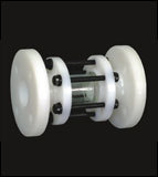
Flow Indicator - Flange End
This precisely developed Flow Indicator - Flange End is used for observation of exact level of water, acid based chemicals, gas and oils. It can also be used for handling salt based gas and liquid. Featured with flange connected design, this flow indicator has extensive applications in different heavy industries. Available in different sizes, this flow indicator conforms to ANSI/DN/JIS norms in terms of its connection design. Observation window of this Flow Indicator - Flange End is made of borosilicate material and quartz glass that are well known for being breakage proof. This flow indicator can be used in less than 280 degree C operating temperature.
| MAX. |
|
|
| Body | Seat | Temp. |
| 150 PSI | 100 PSI | 80oC |
Technical Data
| Construction | 3 piece Design, Full Bore, Borosil Glass, |
| Design & Manufacturings STD | As per Manufacturer's Standard |
| End Connections | Flanged as per ANSI B 16.5 (150#) & as per BS 10(Table D/E/F) & DIN STD. |
Engineering Options:
- S.S. 304/316 parts can be supplied
- Glass Length as per your request
Available M.O.C.:
- PP (POLYPROPYLENE)
- HDPE (HIGH DENSITY POLYETHYLENE)
- ISOTACTIC PP
- PVDF (POLYVINYLIDENE FLUORIDE)
| ALL DIMENSIONS ARE IN MM -------------------------------------------------- (± 2MM) |
| Size | D | D1 | L | T |
|
| IN. | MM |
|
|
|
|
| 3/4" | 20 | 101.0 | 19.0 | 177.0 | 14.0 |
| 1" | 25 | 120 | 24.0 | 191.0 | 20.0 |
| 1.1/2" | 40 | 138.0 | 38.0 | 198.0 | 22.0 |
| 2" | 50 | 163.0 | 50.0 | 220.0 | 24.5 |
| 2.1/2" | 65 | 182.0 | 63.5 | 255.0 | 24.5 |
| 3" | 80 | 200.0 | 75.0 | 267.0 | 26.0 |
| 4 | 100 | 226.0 | 100.0 | 281.0 | 28.0 |
| 6 | 150 | 305.0 | 150.0 | 403.0 | 34.0 |
| No. | Description | Material | Qty |
| 01 | Side Piece/Connector | PP / HDPE / ISOPP / PVDF | 2 |
| 02 | Glass Tube | Glass (Borosil) | 1 |
| 03 | Crisent Ring | PTFE | 2 |
| 04 | Stud | M.S. (EN) / S.S. | Req. |
| 05 | Nut & Washer | M.S. (EN) / S.S. | Req. |
| 06 | Nut Cap | PP / HDPE | Req. |
| 07 | Stud Tube | PVC / PP Coated | Req. |
Robust Construction for Versatile ApplicationsConstructed using high-grade stainless steel, carbon steel, cast iron, or PVC, the flow indicator ensures compatibility with a wide range of media including liquids and gases up to 200C and 10 bar. The toughened borosilicate glass window provides resilience, while the epoxy-coated finish enhances longevityeven in aggressive industrial environments.
Full Visibility and Simple MaintenanceDesigned for optimal operator convenience, this flow indicator features a 360-degree viewing window for clear observation of flow direction and rate, signaled by a rotating paddle or wheel. Its accessible design allows for easy cleaning and maintenance, reducing system downtime and extending operational life.
Flexible Installation Meets Rigorous StandardsSupporting both horizontal and vertical pipeline installations, this indicator connects via drilled flanges conforming to ANSI, DIN, or JIS standards. Available in standard or custom sizes (15mm300mm), it meets international safety and quality benchmarks, making it ideal for critical process control applications.
FAQs of Flow Indicator - Flange End:
Q: How does the Flow Indicator display the flow direction and rate in a pipeline?
A: The flow indicator features a visible rotating paddle or wheel inside a 360-degree toughened borosilicate glass window. As fluid or gas passes through, the paddle or wheel spins, providing an easy-to-read visual indication of both flow presence and direction.
Q: What types of media and industries are suitable for this Flow Indicator?
A: This flow indicator is compatible with a variety of liquids and gases, making it ideal for use in chemical processing, pharmaceuticals, food and beverage, water treatment, and oil & gas industries. Its robust construction supports process temperatures up to 200C and pressures up to 10 bar.
Q: When should the Flow Indicator be installed horizontally versus vertically?
A: The indicator is engineered for flexible installation in either horizontal or vertical pipelines, depending on system requirements and available space. The paddle and visibility mechanism function identically in both orientations for reliable performance.
Q: Where can the Flow Indicator be integrated within a process system?
A: It can be installed anywhere in a pipeline where monitoring flow is essentialsuch as inlet and outlet lines, process loops, or near equipment requiring assurance of continuous flow. The flange-end design offers secure attachment to existing piping systems conforming to ANSI, DIN, or JIS standards.
Q: What is the process for maintaining or cleaning the Flow Indicator?
A: The design includes accessible components, enabling easy removal of the glass viewing section for routine cleaning or inspection. This helps maintain clear visibility and ensures accurate flow monitoring, minimizing potential maintenance downtime.
Q: How does the Flow Indicator ensure safety and reliability in operation?
A: Each unit undergoes hydrostatic leakage testing and uses durable sealing materials like PTFE, EPDM, or Viton gaskets. The borosilicate glass is designed to withstand mechanical and thermal stresses, providing safe, leak-free operation even under demanding conditions.
Q: What are the key benefits of using this Flow Indicator in industrial applications?
A: Users benefit from real-time, 360-degree flow visibility, easy maintenance, robust construction, flexible installation, compliance with major international standards, and suitability for both standard and specialized process requirements.
 Mon - Sat 8:00 - 6:30, Sunday - CLOSED


 Send Email

 Send Inquiry
 Send SMS
 Call Me Free